Environmental Monitoring Art Display Using TCP/IP for sensor communication
Introduction
Note: This will talk about key details about the project, but will focus on my contributions, however, much of the code was co-contributed by myself and another person.
In the last 5 weeks of my 2nd year design course, APSC 200, my team consisting of 5 people were given a task to create an Art display that raises awareness for environmental issues. This was meant to be accomplished by having it interact with the world through sensors and react accordingly. When my team got the idea, we quickly began drafting possible ideas for this, but landed on one of the largest issues, water quality. For the art display, we decided to place it near a river which was fairly polluted and have the art piece be a beaver due to its significance to the local indigenous people in the area. The beaver would nod up and down and wag its tail depending on the water quality metrics decided (pH, Total Dissolved Solids (TDS), Temperature), thus indicating how “happy” it is.
The Problem
Although this idea seemed interesting to us, there was a key problem. It is meant to be an art piece to raise awareness, yet if wired traditionally, it would need to be in the middle of a river, thus not seen. To solve this, we decided to create 2 separate systems. The first would be the sensor housing. This would have the three sensors listed prior, along with an ESP32 which would allow data to be wirelessly transmitted. Then the second would be the art piece which would house an Arduino (As per the requirement of the course) with an ESP Wi-Fi module attached to it. To separate the work, three group members took up the 3D modelling and two (including me) were put on to program the two microcontrollers and get them to communicate.
Design Process
The first step to get this to work was to test all sensors individually, luckily, they all had fairly good documentation so this was fairly simple. After confirming the sensors worked and calibrating them, we started working on the wifi code.
The way the Wi-Fi was set-up was making a TCP server on the ESP32 which could be connected to and then have an IP and port which could be used to communicate between the microcontrollers on the network. While starting out, however, we just set up the code for the esp32 and would connect into it on a laptop to see if we could communicate with it. The following code snippet shows the initialization of the server
1
2
3
4
5
6
7
8
9
10
11
12
13
14
15
16
17
18
19
20
21
22
23
24
25
#include <Arduino.h>
#include <WiFi.h>
#include <stdint.h>
#include "streamTools.h"
#include "sensorRead.h"

#define SSID "SSID"
#define PWD "password"
const uint8_t numChar = 128;

WiFiServer server(333); //Set server to port 333
IPAddress local_IP(192,168,4,1); //Set ESP static IP
IPAddress gateway(192, 168, 4, 1);
IPAddress subnet(255, 255, 255, 0);

void setup() {
  Serial.begin(9600);

  WiFi.softAPConfig(local_IP, gateway, subnet);
  while(!WiFi.softAP(SSID,PWD)) { //Create AP
    delay(100);
  }
  Serial.println("Network started");
  server.begin();
}
In this, softAP is just setting the IP to the pre-set one to ensure it stays static
The next element of the code is the loop logic which ensures it stays stable throughout operation. It starts by checking if anything is connected and checking for any incoming or outgoing messages
1
2
3
4
5
6
7
8
9
10
11
12
13
14
15
void loop() {
WiFiClient client = server.available(); //Create client object
  if(client) Serial.println("Client connected");
  char buffer[numChar]; //Incoming data buffer
  uint8_t buffIndx = 0;
  char inMsg[numChar]; //Incoming data string
  inMsg[0] = '\0';
  char outMsg[numChar]; //Outgoing data string
  outMsg[0] = '\0';
  sensorData sensor = {0};

  uint32_t currMicros, currMillis, startMicrosRead, startMillisTimeout, startMillisSensor;
  startMicrosRead = micros();
  startMillisTimeout = millis();
  startMillisSensor = millis();
Then, once connected, it will check for messages every second to see if anyone has asked for a sensor request, which would cause it to give sensor data. After 5 seconds of no answer it kicks everyone off the network to protect against an infinite loop happening which could break the art piece
1
2
3
4
5
6
7
8
9
10
11
12
13
14
15
16
17
18
19
20
21
22
23
24
25
26
27
28
29
30
31
32
33
34
35
while(client.connected()) {
    currMicros = micros();
    currMillis = millis();

    if((uint32_t)(currMillis - startMillisTimeout) > 5000) break; //Set TCP connection timeout to 500 seconds

    if((uint32_t)(currMicros - startMicrosRead) > 1000) { //Look for incoming messages
      if(streamRead(client,buffer,sizeof(buffer),&buffIndx)) {
        strncpy(inMsg,buffer,sizeof(inMsg));
        buffer[0] = '\0';
        buffIndx = 0;
      }
      startMicrosRead = micros();
    }

    if((uint32_t)(currMicros - startMillisSensor) > 40) { //Update TDS ADC reading array every 40 ms
      updateTDSArr(&sensor);
      startMillisSensor = millis();
    }

    if(inMsg[0] != '\0') { //Check if incoming message is available
      if(strstr(inMsg,"senseReq")) { //Respond with sensor readings when asked
        getTDS(&sensor);
        getPH(&sensor);
        getTemp(&sensor);
        sniprintf(outMsg,sizeof(outMsg),"%s,%s,%s\r\n",sensor.TDSString,sensor.pHString,sensor.TempString);
        client.print(outMsg);
        outMsg[0] = '\0';
      }
      else if(!strstr(inMsg,"ACK")) client.print("ACK\r\n");
      Serial.print(inMsg);
      inMsg[0] = '\0';
      startMillisTimeout = millis();
    }
  }
Then on the client side (The Arduino) there was a separate script which would take the data from the server’s sensors, and then use that to modify the actuators (2 servos for TDS and a LED Ring for pH). Despite the simple premise, this was one of the most difficult parts of the entire project as there were many things about each individual sensor that made it difficult to implement with the network. A good example of this is the LED Ring. To display and colour on the ring, you need to use the following command
1
LED.show()
This command completely broke the code over and over despite what we did to try to change it. After looking at the documentation we found the issue; it said it would mess with all internal delay timers by approx 30-40ms and that “there is no trivial solution for this”. Since The TCP network we made is heavily time dependent, this command running every loop was causing a large delay which ended in the system failing. To fix this, we only ever allowed it to update if there was a large colour change (change in pH), and it needed to be a certain amount of time since the last update.
1
2
3
4
5
6
7
8
9
10
11
if(((ring.Red != lastRingColour.Red || ring.Green != lastRingColour.Green || ring.Blue != lastRingColour.Blue))
      && (uint32_t)(data.currMillis - startMillisRing) > RING_UPDATE_MS) {
      for(uint8_t i = 0; i < NUM_PIXELS; i++) {
        RING.setPixelColor(i, RING.Color(ring.Red,ring.Green,ring.Blue));
      }
      RING.show();
      lastRingColour.Red = ring.Red;
      lastRingColour.Green = ring.Green;
      lastRingColour.Blue = ring.Blue;
      startMillisRing = data.currMillis;
    }
To know if the Client was connected was another issue as the Arduino only has 1 TX RX port meaning serial wouldn’t work when WIFI is connected. To solve this, we created a state machine which would show the network state on the LEDs those being Wi-Fi connecting, TCP connecting and Server Reading.
1
2
3
4
5
6
7
8
9
10
11
12
13
14
15
16
17
18
19
20
21
22
23
24
25
26
27
28
switch(nextState) {
      case WIFI_CONNECT:
        ring.Red = 255;
        ring.Green = 0;
        ring.Blue = 0;
        break;
      case TCP_CONNECT:
        ring.Red = 245;
        ring.Green = 20;
        ring.Blue = 10;
        break;
      case SERVER_READ:
        if(data.pH >= 7.0) { //Map for basic, blue->green
          ring.Red = 0;
          ring.Green = mapf(constrain(data.pH,7.0,10.0), 7.0, 10.0, 60.0, 255.0);
          ring.Blue = mapf(constrain(data.pH,7,10), 7.0, 10.0, 250.0, 0.0);
        } else { //Map for acidic, blue->yellow
          ring.Red = mapf(constrain(data.pH,4,7), 7.0, 4.0, 0.0, 250.0);
          ring.Green = mapf(constrain(data.pH,4,7), 7.0, 4.0, 60.0, 220.0);;
          ring.Blue = mapf(constrain(data.pH,4,7), 7.0, 4.0, 250.0, 20.0);
        }
        break;
      default:
        ring.Red = 0;
        ring.Green = 0;
        ring.Blue = 0;
        break;
    }
An example of what happens in one of the states is the following for the WIFI_CONNECT case:
1
2
3
4
5
6
7
8
9
10
11
12
13
14
15
16
17
18
clientStates stateWiFiConn(clientData* data) {
  if((uint32_t)(data->currMillis - data->startMillisSend) > 1000) {
    snprintf(data->cmd,sizeof(data->cmd),"AT+CWJAP=\"%s\",\"%s\"\r\n",SSID,PWD); //Attempt to connect to wifi network
    Serial.print(data->cmd);
    data->cmd[0] = '\0';
    data->startMillisSend = data->currMillis;
  }
  if(streamRead(Serial,data->buffer,sizeof(data->buffer),&data->buffIndx)) { //Look for incoming messages
    strncpy(data->inMsg,data->buffer,sizeof(data->inMsg));
    data->buffer[0] = '\0';
    data->buffIndx = 0;
  }
  if(data->inMsg[0] != '\0') {
    if(strstr(data->inMsg,"ERROR")) return START; //Reset if error
    if(strstr(data->inMsg,"WIFI CONNECTED") || strstr(data->inMsg,"WIFI GOT IP") || strstr(data->inMsg,"OK")) return TCP_CONNECT; //Check if connected successfully
  }
  return WIFI_CONNECT;
}
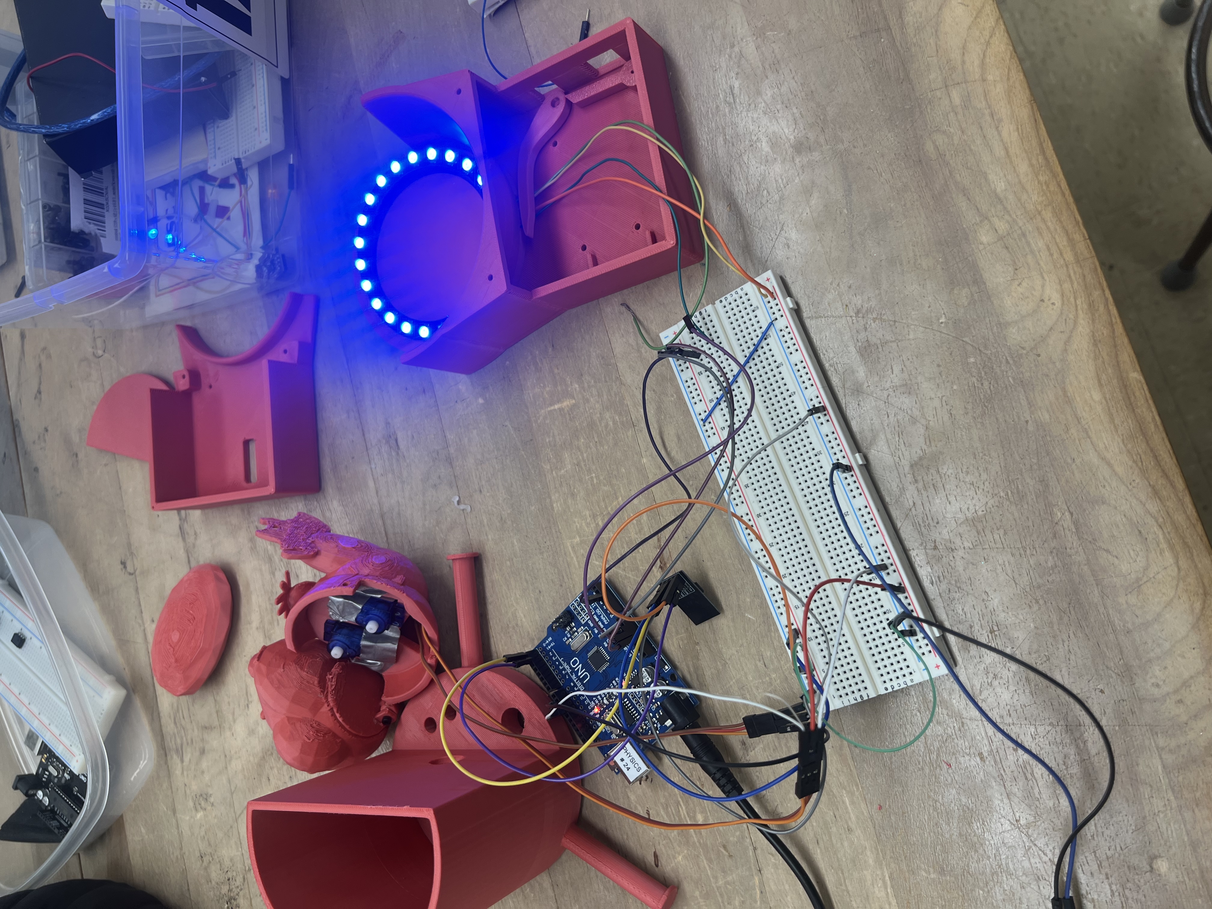
Once connected, the server would send the sensor data whenever the Client requested sensereq this would all happen using AT commands which was chosen due to the strong documentation allowing us to learn how to use it quickly, which the Client could then read and use to move the servos or change the LED colour. The following are some photos and videos showing the art installation prototype in a fully operational way:
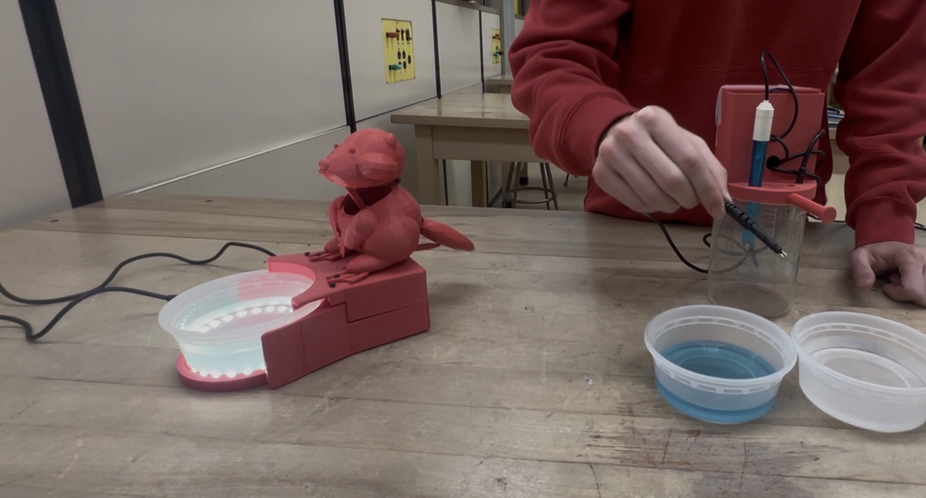
Below is what happens when the pH sensor is put into a basic (Blue) neutral (clear) and acidic (red) solution, and how the LEDs react accordingly, as you can see, there are no wires between the sensors and the art display
Here the response to changes in TDS is shown, in the air, the TDS is about 0 and in the water it’s about 100, which causes the tail speed to halve when placed in the water.
Although there is plenty more to talk about with this project, I got to the key points, and if you are curious, you can always ask me questions about how we did any other part of the design.
Reflection
This was an interesting one since it is a prototype we took a lot that we could apply to the theoretical final version, such as using metal over plastic, using cellular over Wi-Fi but overall, the core concept works well here, and should be applied in a similar way. In the future, doing more organized tests to troubleshoot would also be a better way to figure out what went wrong compared to the large amount of guesswork that had to happen this time around. But overall, this project worked out quite well.