Creating a Robotic Arm
Introduction
An engineering project that has been a goal of mine for a long time is making a device inspired by biology. Whether that be an arm, hand or something unrelated, the idea seemed like it could be a fun challenge which could develop my problem-solving abilities while making something that could have a useful application. After some thought, I landed on building a robot arm due to the versatility that it could bring.
Brainstorming
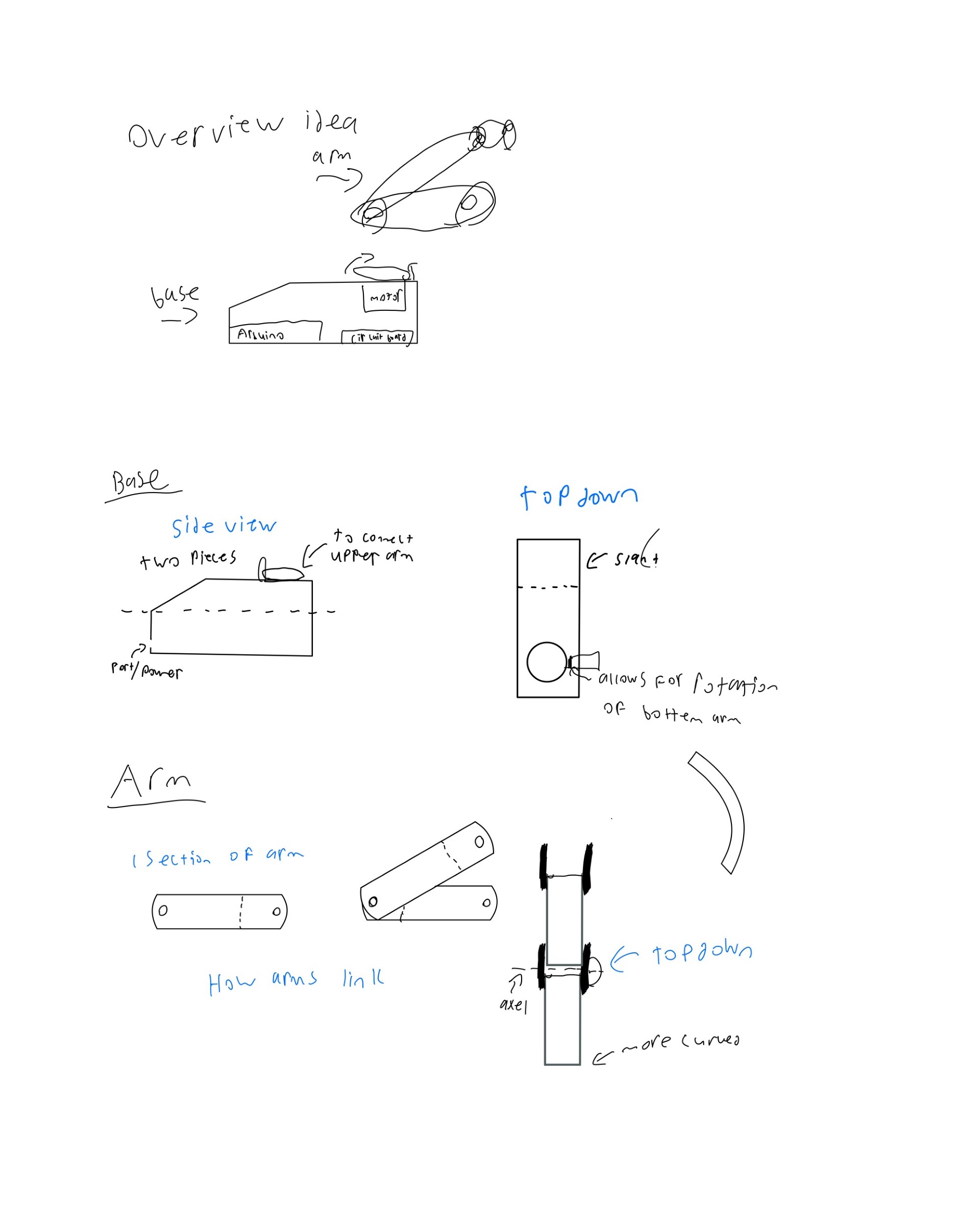
There are several factors to consider when making a robot arm. First of all, the size of the arm helps to narrow the goal of the arm. Then once determined, the number of joints is vital to decide on so the CAD model can be developed to incorporate the proper number of motors, and moving parts. After all is decided, sketching a rough idea followed by creating a meticulous and refined CAD model would lead to the highest likelihood of success. As for the arm I decided to make, I wanted it to be desktop sized to easily take apart, and I decided on 5 joints. Below is an early rough sketch which would help to inspire the CAD model in later parts.
Design Process
When it came to actually designing the arm in CAD, Onshape was chosen due to the ability to work anywhere, including on weak laptops. As there were many pieces to this build, the following is an overview of the thought that went into designing the most important pieces.
Base
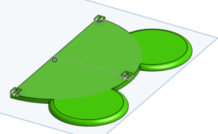
Since the robot arm would run off of 5 servo motors which need to move independently of one another; and an Arduino is unable to support that many PWM components alone, a servo controller was used alongside an Arduino Mega. Due to this, Both the shape of the Arduino and the motor controller needed to be considered when designing the base, in order to allow for a secure fit. This is shown in the photo below.
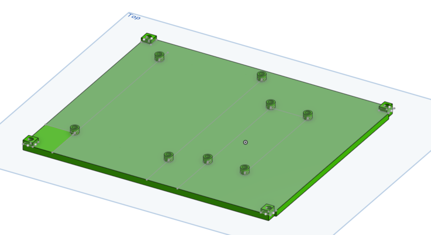
To add further stability, a second piece was added to the base which would act to prevent the arm from falling over during movement.
These base pieces would need to connect to an arm stand which would hold the actual arm, and allow for rotation. Due to this, there needed to be room both for wiring and a servo within this arm stand. The design I landed on is shown below.
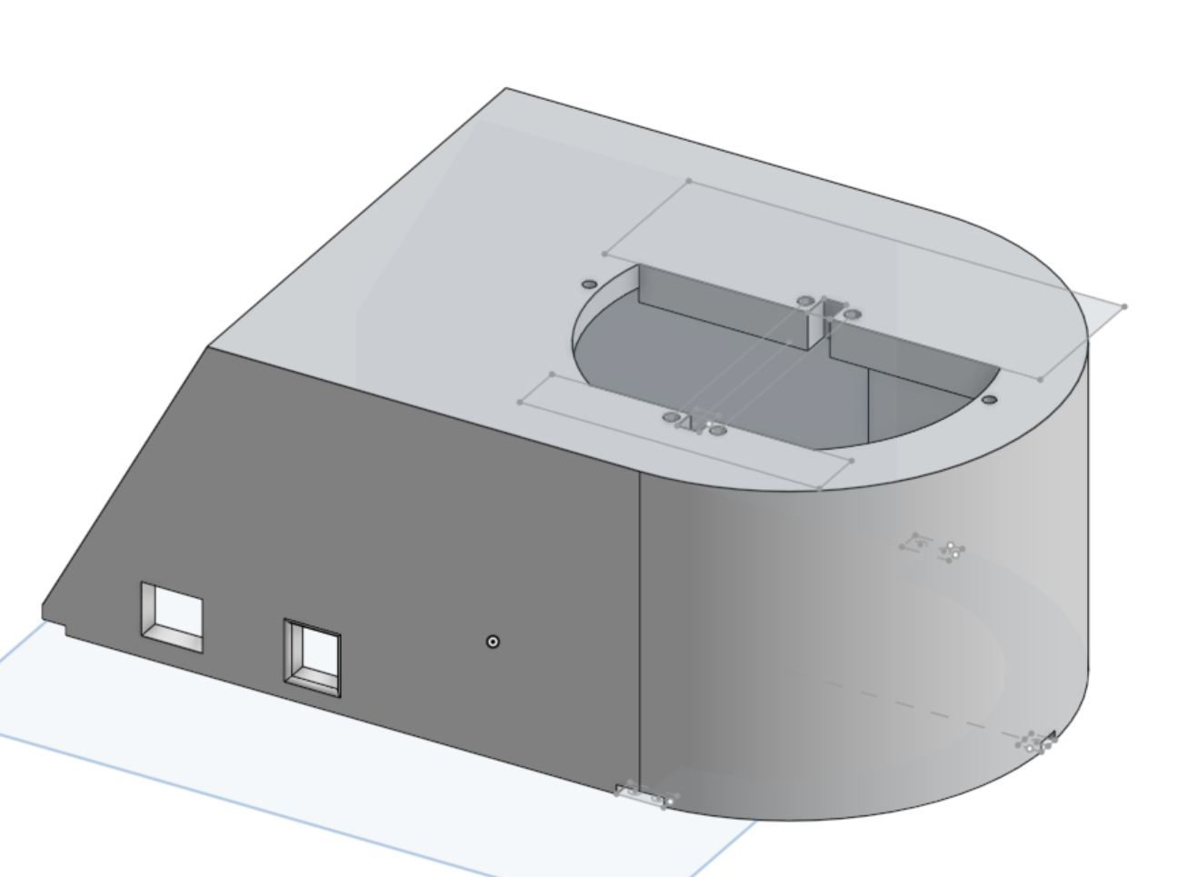
Each of these base pieces fit together using M2.5, which is one of the most common screw types making it easy to find and replace if/when problems arise.
First Joint
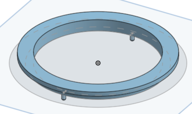
The first joint of the arm allows for the rotation. This is done through a servo mounted in the base. However a design challenge came when trying to make the spinning mechanism stable. As if it is only held on by the motor’s axle, it would wobble and be unsecure. The solution to this was creating a circle which the mechanism could rotate around. This could then be secured into the base with press fits
As for the actual spinning pieces, they needed to have a component tall and strong enough to support the rest of the arm, along with sufficient space to allow for cables, as keeping the cables neat and together is important.
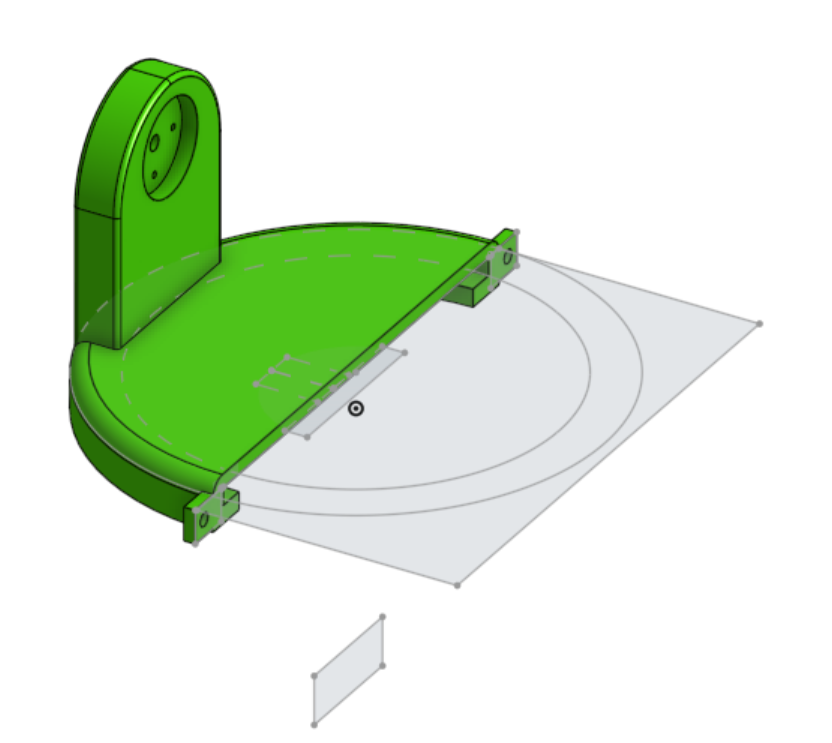
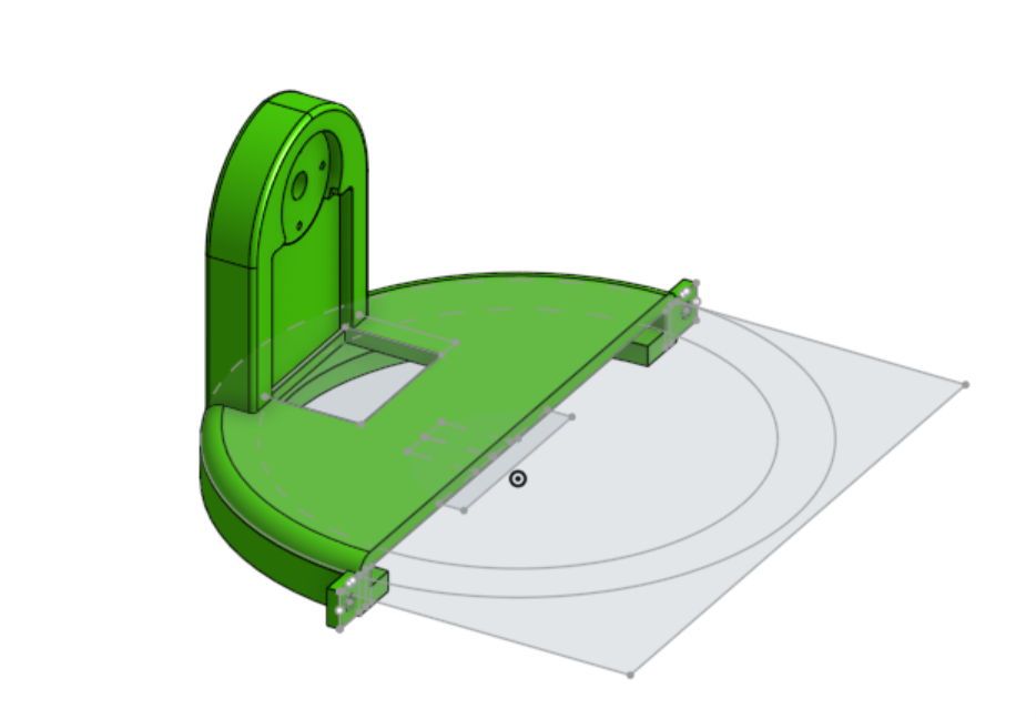
When all pieces shown so far are placed together, the spinning should work as such:
Second and Third Joints
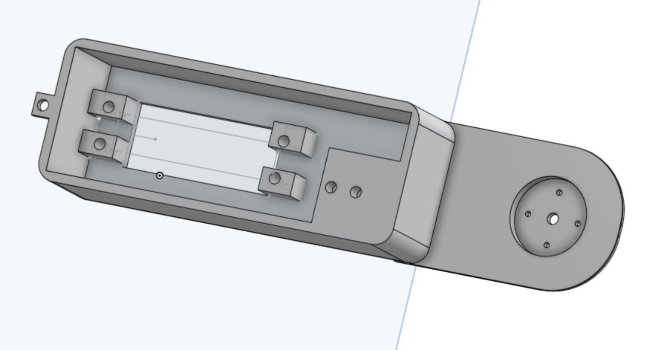
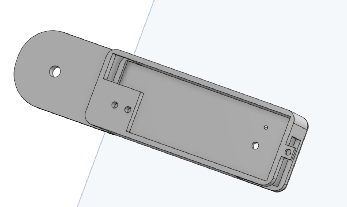
These two joints allow for the actual arm-like movement. These were made by having a servo mount on the inside which connects to the outside and allows the axle to go into a servo horn which is screwed in place, causing the arm to move. Then at the end of the arms, there is another connection component for the next piece. Another important element which aided organization was creating holes which allow for wires to travel the whole way through so the servos at the top are able to be plugged in.
Wrist and End Effector
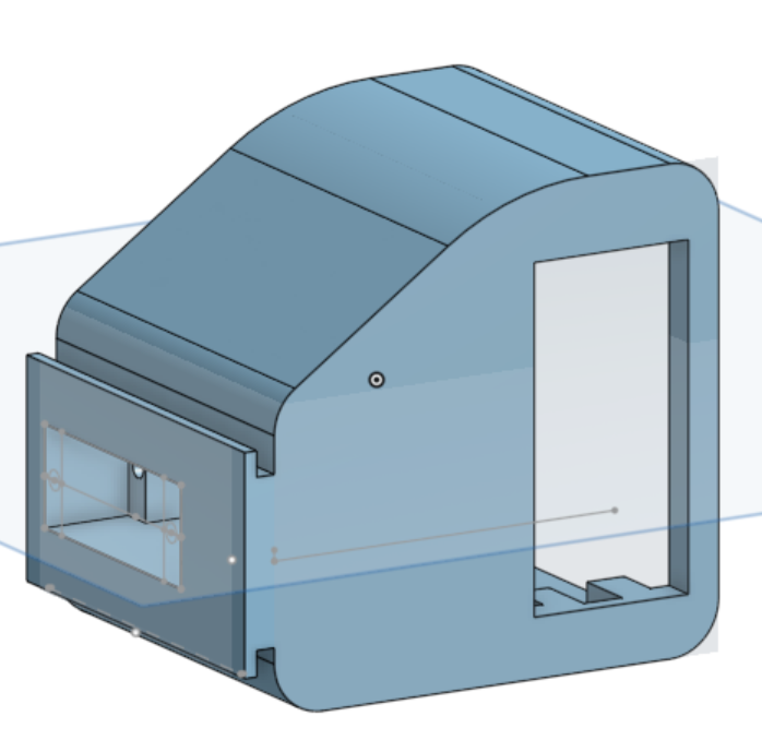
The wrist and end effector being one piece was a design element I chose to allow for fewer pieces while keeping a similar functionality. When making this piece, as there needs to be a full size servo for rotating the wrist along with a micro servo for the end effector. This makes the wrist appear bulky, however through fillets I made the appearance a little bit more reasonable.
The Completed CAD
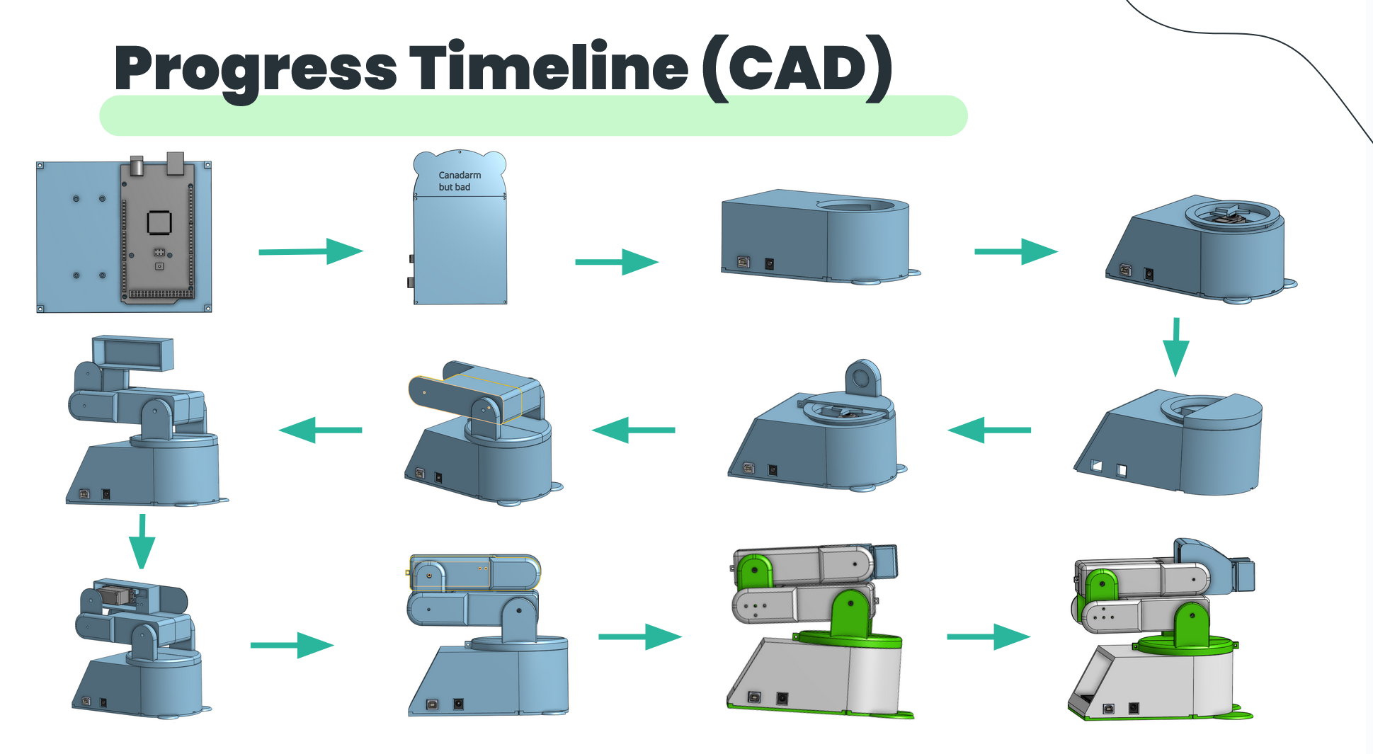
As I went, I put the parts together with the proper joints to simulate what the robot would look like once I finished building.
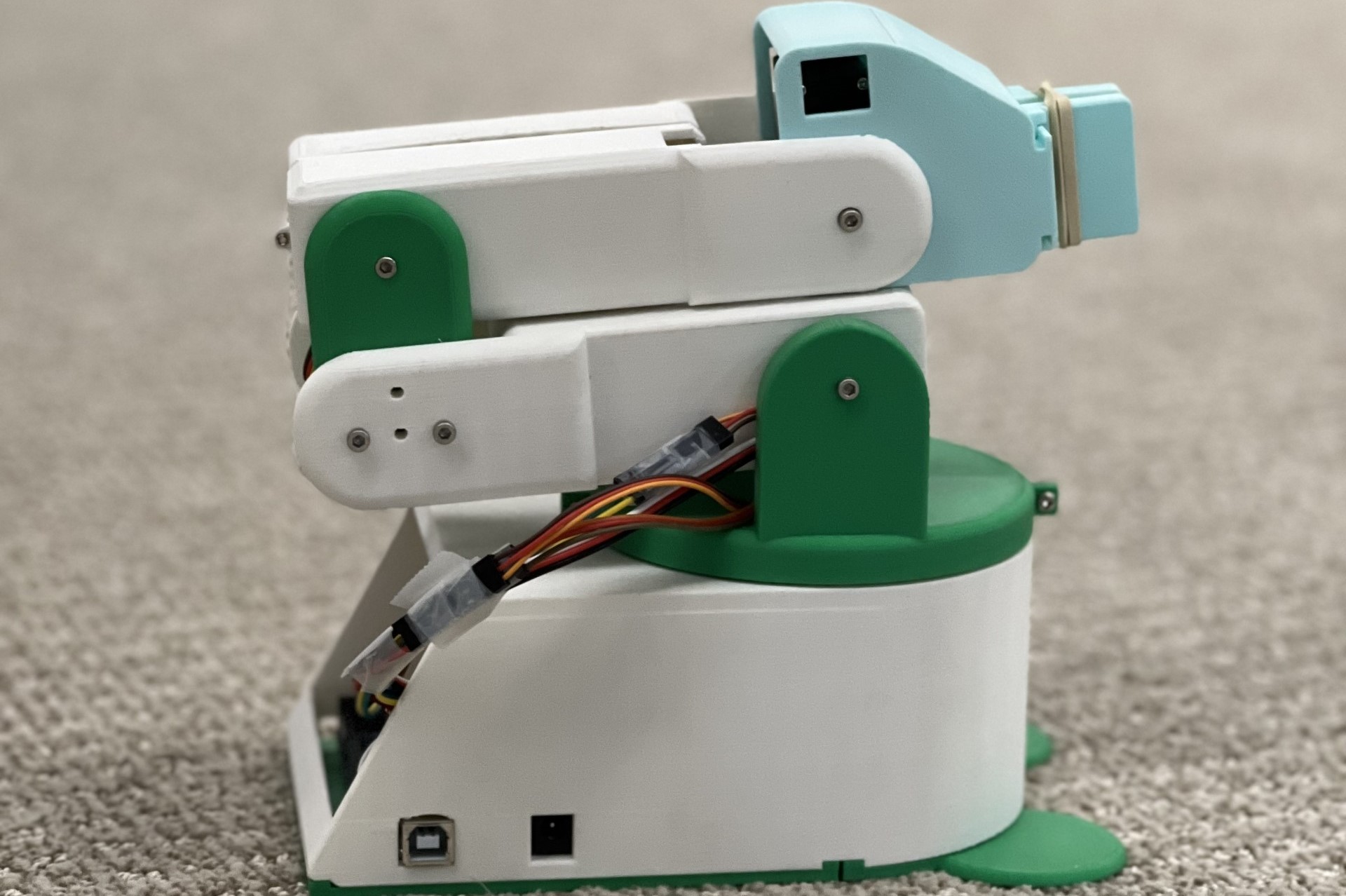
The progress and finished arm are both shown below.
Building
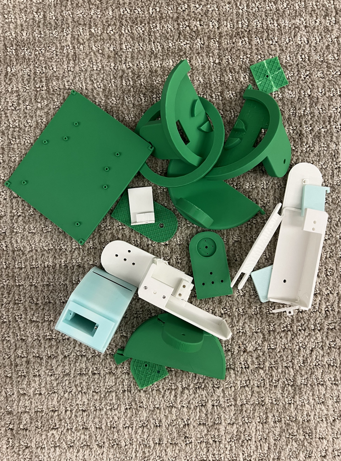
To build the arm, I printed all of the parts out and screwed them together with minimal hassle.
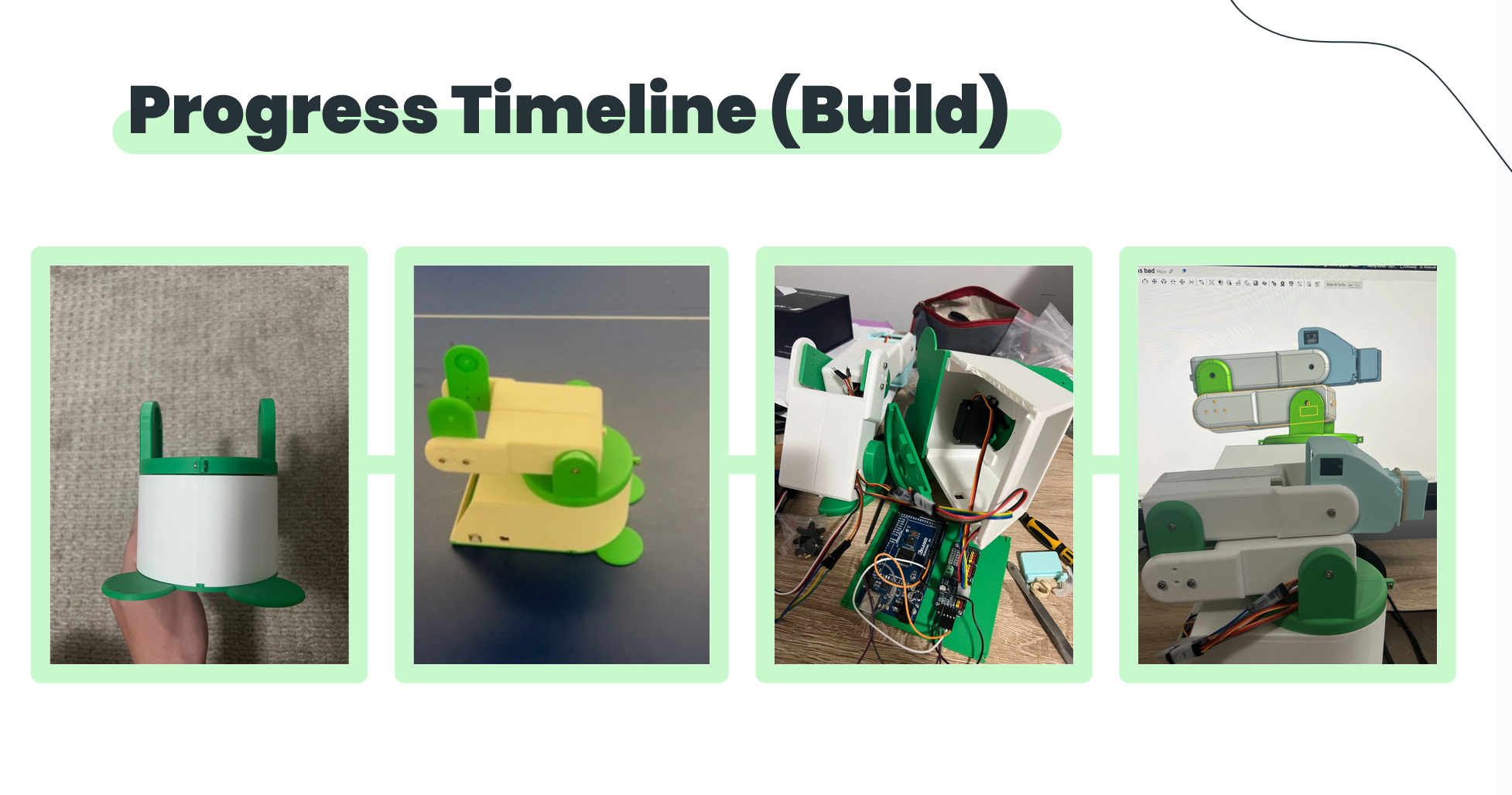
Despite this, there were plenty of failed parts which made me go back to the drawing board and redesign some parts a few times before they worked properly.