The Full VEX Design Process (Spin-Up)
Introduction
For my third year in VEX robotics, I wanted to improve my performance from previous years. To do this, much more planning and rigor went into each step of the design process, which will be shown below.
Starter Ideas
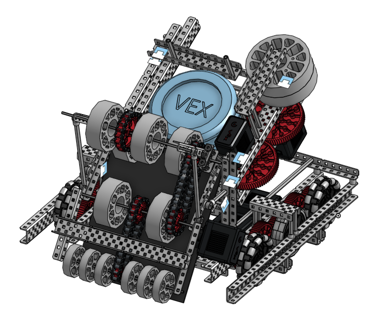
After first seeing the game announcement, I immediately got to work writing down plausible ideas and discussing the intricacies of the game. After having some time to let the idea of the game, I created the CAD model shown below:
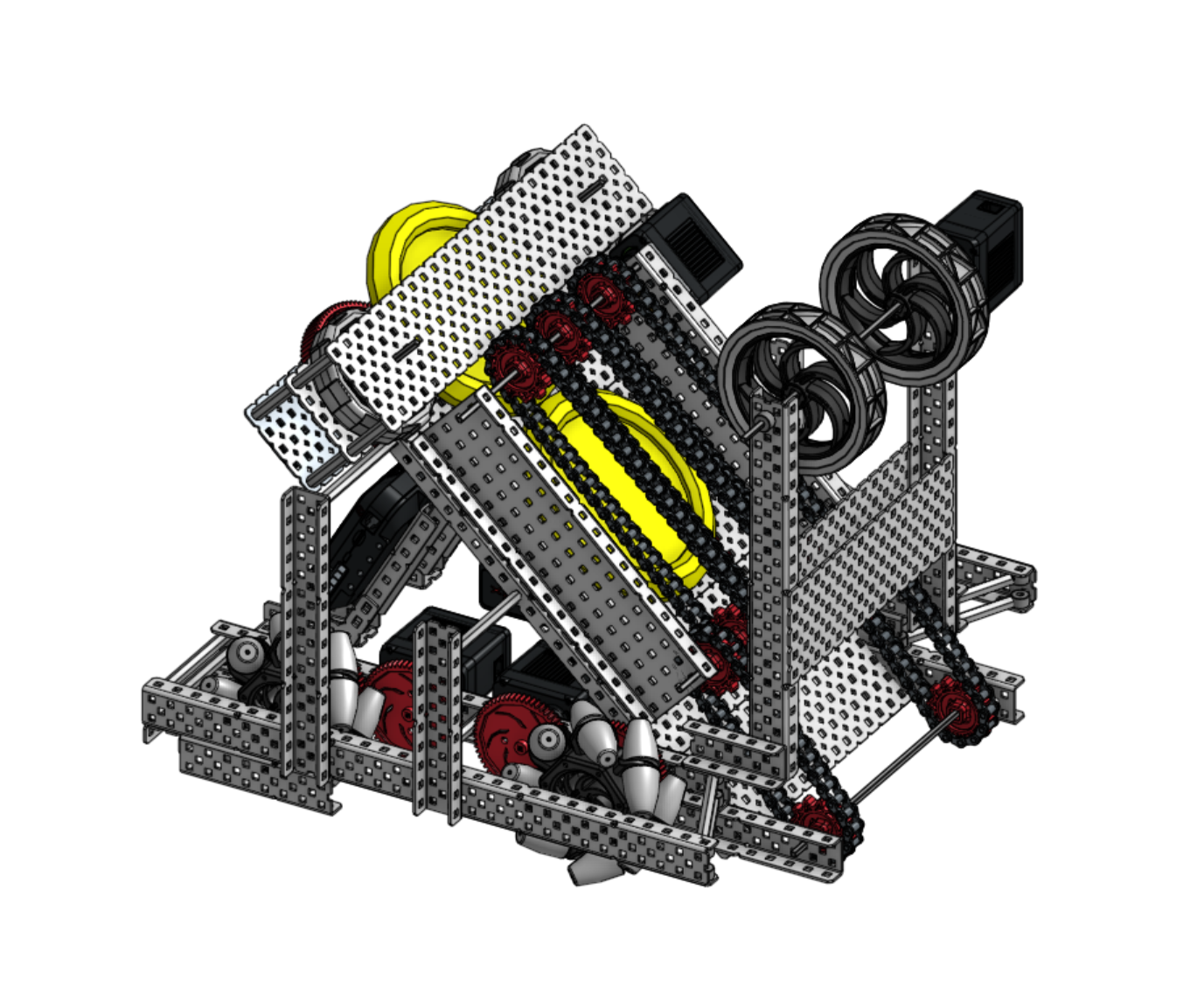
This design had benefits such as
- Mecanum wheels allowing for easy strafing
- 4 wheel drive for extra torque on the drive train
- Simple flywheel Mechanism likely easy to repair if damaged
- Dual Flywheel system for added compression
However, after thinking about it more, core design flaws appeared leading me to consider a redesign, these include:
- Inefficient use of motors
- Difficulties in getting the two flywheels to be identical in speed could lead to weird flight paths
- The mechanism shown for intaking disks likely does not have enough friction to stop sliding
- Due to the Mecanum wheels, the drivetrain is quite slow as extra torque is important.
Although this design could work in theory, I felt it would be much harder to bring to life than if I made a more effective redesign.
Iterations
To make an improved version of the design, I split the tasks into three parts, reflecting the robot’s functionality:
- Base
- Indexer
- Flywheel
Improving the Base
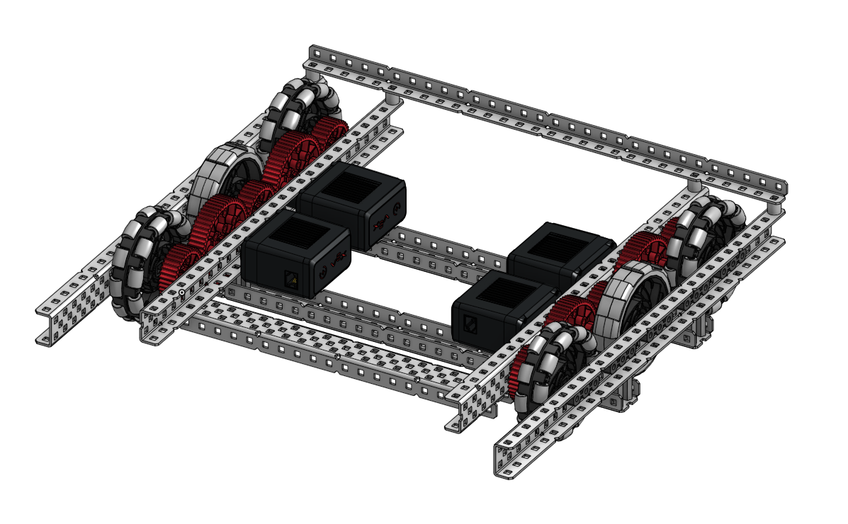
After experimentation, we found that the ideal gear ratio for the drive train was 60:36 for the 200RPM gear box, making it run around 333RPM. Each wheel is then given its own motor to further increase the drivetrain torque. In this design, mecanum wheels were ditched due to the lack of application in this year’s game.
Improving the Indexer
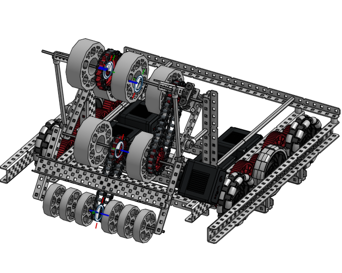
To allow for a more efficient use of motors, the goal of this design was to combine the roller and indexer into the same system. This would be accomplished by connecting chains through several axles to allow for a single motor to be responsible for two jobs.
Improving the Flywheel
As said earlier, the dual flywheel system was clunky for several reasons, leading to a single fly wheel to be used for this redesign which is capable of spinning at 3000RPM. The disk is then sent out by compressing it between the flywheel and a C-channel. A smaller wheel would be used to bring the indexed disks.
Final Design
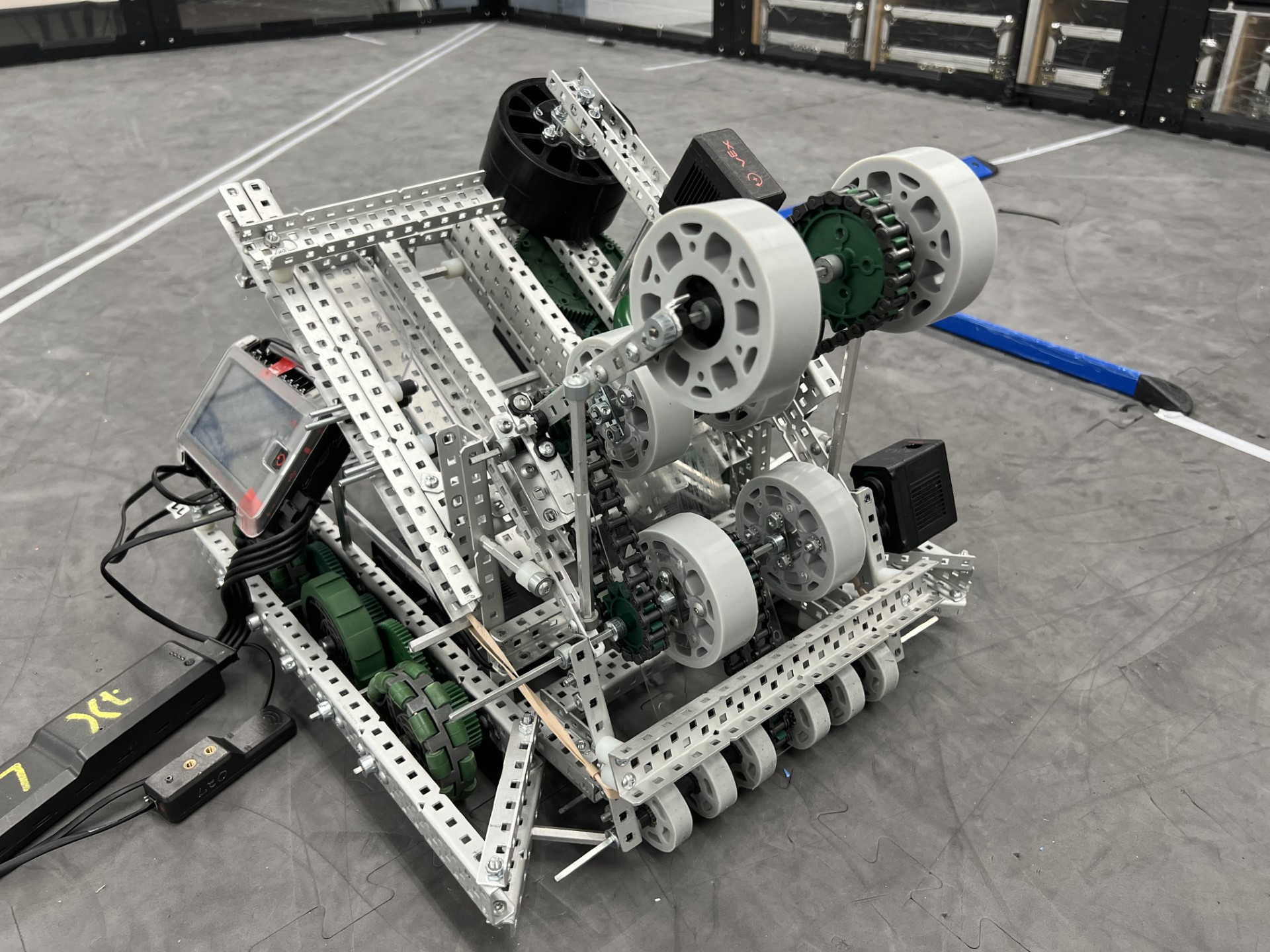
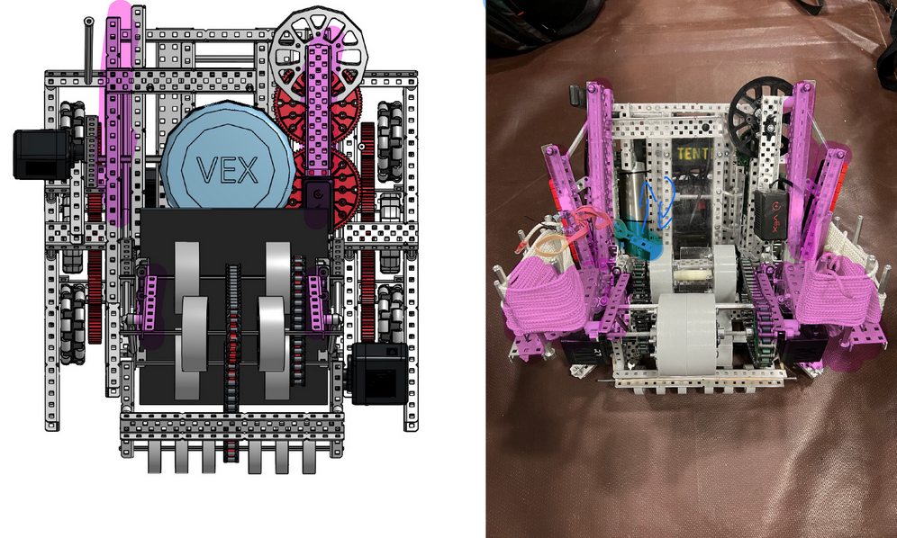
Although the CAD model led the way for building the robot, some last minute additions were made to increase the quality and in game performance. The changes are shown below and include changes to the structure motor placements and flywheel gear ratio.
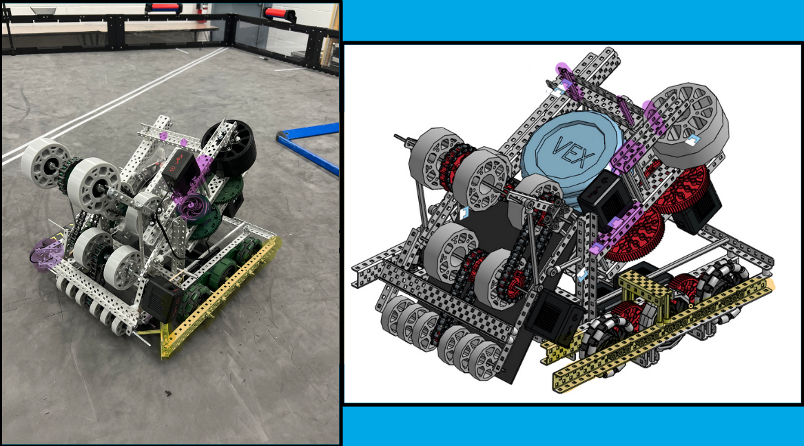
On top of this, we added pneumatics to the robot to fling string onto and across the field to increase points in the endgame. This was a challenge due to the limited space left on the robot, however, with some zipties and extra support beams it was doable.
Calculations for Program
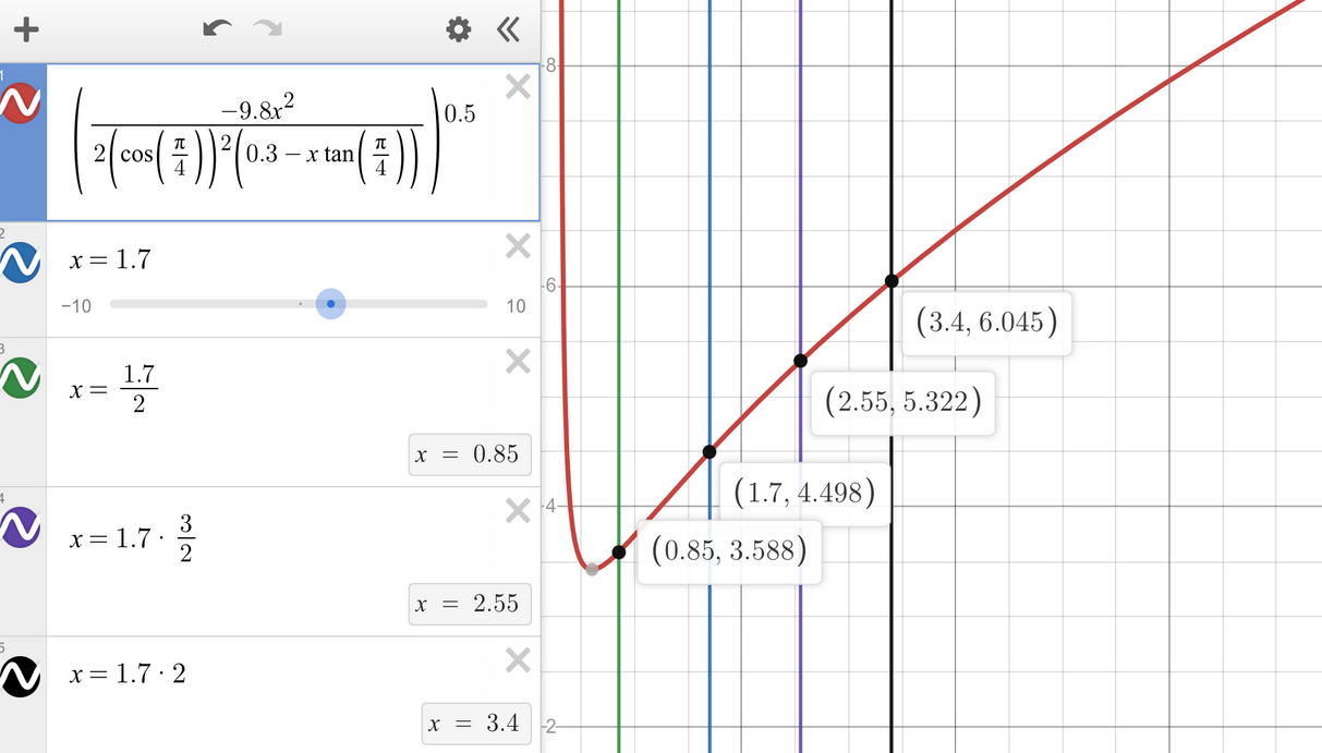
As the robot does not have an adjustable angle for the flywheel, the way it would deal with different distances is by changing the velocity it launches the disks at. To do this, kinematics was employed to see how fast the disk would need to travel at different distances from the net, in order to score.
\[\vec h = v_{iy}t+\frac{1}{2}\vec gt^2\] \[v_{x}=v cos(\theta)\] \[v_{y}=v sin(\theta)\] \[t= \frac {d_{x}} {v_{x}}\] \[\therefore \vec v = \sqrt{\frac{-gd^2}{2(cos\theta)^2(h-dtan\theta)}}\]where g is the acceleration due to gravity, d is the horizontal displacement, and theta is the angle the disk is released. This would then output a initial launch velocity at any distance from the goal creating a graph looking like this:
The Code
Due to the various ways in which the robot may be used, whether it be in a skills run or in tournament, the code used needed to be fine tuned for each part.
Driver Controller
To move the robot as the driver, the input from the joystick would be sent to the robot brain and processed as a percent that it should run the motors at. The drivetrain control type used is tank drive.
1
2
3
4
5
6
7
8
9
10
11
12
13
// void used to take the joy sticks and convert it into movement
void DriveControl::ControllerDrive(int axis1POS, int axis3POS){
//create a dead zone to stop accidental movement
  if(abs(axis3POS) < 5) { axis3POS = 0; }
  if(abs(axis1POS) < 5) { axis1POS = 0; }

  //make the wheels move
  LeftDrive.spin(fwd, (axis3POS + axis1POS) * dir, pct);
  RightDrive.spin(fwd, (axis3POS - axis1POS) * dir, pct);
}

//variable used to change direction on button press
void DriveControl::dirControl() {dir *= -1;}
For the code that runs the flywheel, the flywheel starts gaining speed and then vibrates the controller once at a certain speed to notify the driver that shooting is available.
1
2
3
4
5
6
7
8
void FlywheelControl::spinFlywheel(){
  if (Controller1.ButtonL1.pressing()){
    Flywheel.setVelocity(500, rpm);
      if(Flywheel.velocity(rpm) > 400){
          Controller1.rumble("---");
      }
  }
}
Auto Control
The autonomous used a PID which helps to alleviate the accumulating error and self correct on its path. PIDs are vital in VRC due to the autonomous periods. They ensure the plan pans out as expected, and allow the robot to adapt to slight changes in the environment
1
2
3
4
5
6
7
8
9
10
11
12
13
14
15
16
17
18
19
20
21
22
23
24
25
26
27
28
29
30
31
32
33
34
35
36
37
38
39
40
41
42
43
44
45
46
47
48
49
50
51
52
53
54
55
56
57
58
59
60
61
62
PIDh::PID LeftDrivePID(0.2, 0.001, 2.0), RightDrivePID(0.3, 0.0, 0.5), turnPID(0.23, 0.0, 0.4); //adjust these values in order of: P, I, D
double distances = 0, rotations = 0,   angles = 0, turnPower = 0;
int speed = 100;

int PIDh::PID_run(){
  while(PID_enable){
    if(PID_reset){
      PID_reset = 0;
      LeftDrive.setPosition(0, degrees);
      RightDrive.setPosition(0, degrees);
    }

    turnPID.desired_position = angles; // Set angles to how far it has turned
    turnPID.update(IMU.rotation(degrees)); // use IMU to get the degree
    rotations += turnPID.motorPower; //see how many times the wheel has spun by using the update function from above along with the motorPower

    LeftDrivePID.desired_position = inchesToDegrees(distances) + rotations;
    RightDrivePID.desired_position = inchesToDegrees(distances) - rotations;

    LeftDrivePID.update(LeftDrive.position(degrees));
    RightDrivePID.update(RightDrive.position(degrees));

    LeftDrive.setVelocity(LeftDrivePID.motorPower * speed / 100, percent);
    RightDrive.setVelocity(RightDrivePID.motorPower * speed / 100, percent);

    LeftDrive.spin(forward);
    RightDrive.spin(forward);

    task::sleep(20);
  }
  return 0;
}

task shootDisk(){
  Flywheel.setVelocity(80, percent);
  for(int i = 0; i < 3; i++){

   if (Flywheel.velocity(rpm) > 450){
    cylinderIndex.set(true);
    wait(500, msec);
    cylinderIndex.set(false);
   }
  }
      Flywheel.stop(coast);
  return 0;
}

void PIDh::AutoLeft(){
  angles -= 90;
  shootDisk();
  distances+= 15;
  wait(400, msec);
  distances-= 15;
}

void PIDh::AutoRight(){
//To be completed
}

void PIDh::AutoSkills(){
//To be completed
}
Then, to pick between the different autonomous in different situations, a UI was shown on the brain which allows for a click to decide on the autonomous that is chosen.
1
2
3
4
5
6
7
8
9
10
11
12
13
14
15
16
17
18
19
20
21
22
23
24
25
26
27
28
29
30
31
32
33
34
35
36
37
38
39
void Picker::AutoPick(){
  // Print 3 rectangles
  for (int i = 0; i < rect_amount; i++) {
    color current_color;
    // Check if i is AutonNumber to change current_color
    if (i+1 == AutonNumber) {
      current_color = selected;
    } else {
      current_color = unselected;
    }
    Brain.Screen.setPenColor(blue);
    Brain.Screen.drawRectangle(x1+(spacing*i), y1, x2, y2, blue);
  }
// Set font to monoM
  Brain.Screen.setFont(monoM);

  while (true) {

    // Selected position
    int x = Brain.Screen.xPosition(); // X position of finger
    int y = Brain.Screen.yPosition(); // Y position of finger

    // Check if finger is within vertical selection of the boxes
    if (y1 < y && y < y1+y2) {
      for (int i = 0; i < rect_amount; i++) {
        // Check which x value the finger is within
        if (x1+(spacing*i) < x && x < (spacing*(i+1))-x1) {
          AutonNumber = i+1;
        }
      }
    }

    // Print AutonNumber to brain
    Brain.Screen.setPenColor(selected);
    Brain.Screen.printAt(5, 30, "Current Auto: %d", AutonNumber); // %d is a formatting character that gets replaced with AutonNumber
    wait(20, msec);
    Brain.Screen.clearLine(1);;
  }
}